Connecting RS485 Modbus devices
Introduction
RS485 is the physical interface and Modbus is the protocol used over this interface. It is reliable, simple and offers many possibilities. The devices that need to be read or controlled can be connected as a serial bus to the Envi.Baseenvi.base De energiecontroller van Envitron die apparaten uitleest, aanstuurt en data opslaat achter de hoofdaansluiting. via the Modbus RS485 port. The Envi.Baseenvi.base De energiecontroller van Envitron die apparaten uitleest, aanstuurt en data opslaat achter de hoofdaansluiting. acts as the mastermaster Het apparaat dat de communicatie initieert en bepaalt welk slave-apparaat wanneer antwoordt. in the bus network. A maximum of 32 devices can be connected to a single RS485 line.
Are there multiple devices on site that need to be read and are far apart, or is the RS485 bus very slow? A RS485-to-TCP converter may provide a solution, allowing communication to take place over the network: Contents of box.
Connecting RS485 devices
For connecting RS485 devices to the Envi.Baseenvi.base De energiecontroller van Envitron die apparaten uitleest, aanstuurt en data opslaat achter de hoofdaansluiting., an optional 2-metre RJ45 cable is supplied with ferrules on one end. You can also choose to make this cable yourself. For this, refer to the Data connections page. For longer distances, a shielded twisted-pair cable is always used.
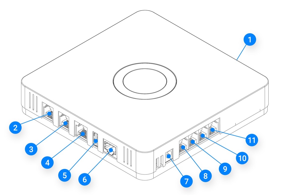
The Envi.Baseenvi.base De energiecontroller van Envitron die apparaten uitleest, aanstuurt en data opslaat achter de hoofdaansluiting. has two RS485 Modbus ports: port 1 with an RJ45 connector and port 2 with an RJ12 connector; the latter is not standard on the Envi.Baseenvi.base De energiecontroller van Envitron die apparaten uitleest, aanstuurt en data opslaat achter de hoofdaansluiting.. When the second RS485 port is required, this must be agreed upon in advance with the sales department.
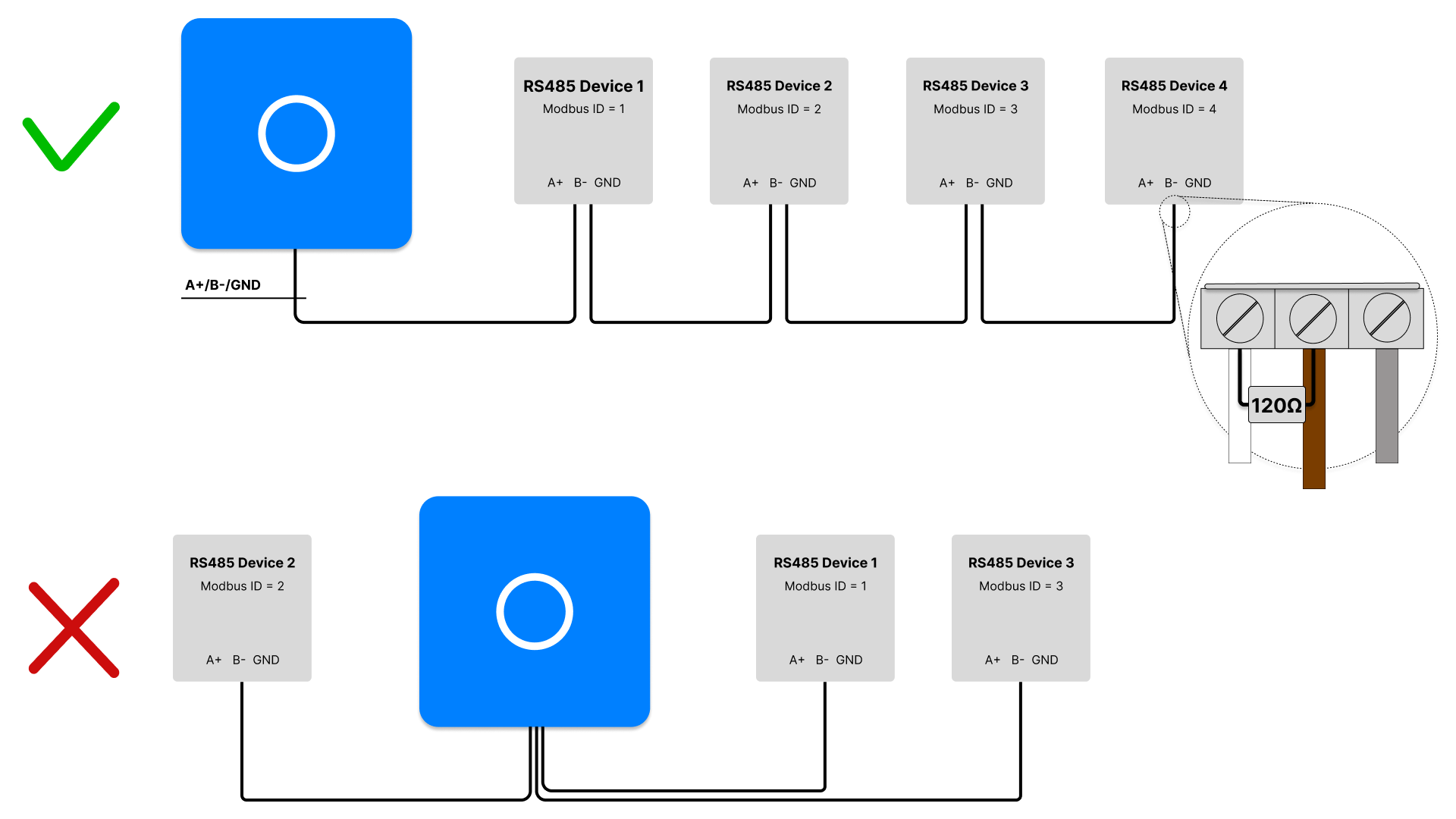
All RS485 devices must be connected in series to the Envi.Baseenvi.base De energiecontroller van Envitron die apparaten uitleest, aanstuurt en data opslaat achter de hoofdaansluiting.: A+ to A+ and B− to B−, looped through from device to device. See also the image below. The Envi.Baseenvi.base De energiecontroller van Envitron die apparaten uitleest, aanstuurt en data opslaat achter de hoofdaansluiting. is the mastermaster Het apparaat dat de communicatie initieert en bepaalt welk slave-apparaat wanneer antwoordt. and a maximum of 32 devices can be connected to one bus. At the last device in the bus, a 120 Ω termination resistor must be placed between A+ and B− to prevent reflectionsreflectie Weerspiegeling van datasignalen op een kabel, waardoor storingen en foutmetingen kunnen ontstaan. on the line. A ¼ Watt, 120 Ω resistor is typically used for this purpose. Some devices have a built-in internal termination resistor that can be activated with a switch. This may only be enabled on the last device in the bus. On the Envi.Baseenvi.base De energiecontroller van Envitron die apparaten uitleest, aanstuurt en data opslaat achter de hoofdaansluiting. side, the termination resistor is already internally present.
When a device has no connection for the reference wire (GND), it does not need to be connected there. In that case, ensure that at the next device the shielding and any drain wire are reconnected, so that the RS485 bus maintains the same potential level throughout and is less susceptible to interference.
When the Envi.Baseenvi.base De energiecontroller van Envitron die apparaten uitleest, aanstuurt en data opslaat achter de hoofdaansluiting. is ordered as a complete installation cabinet, the communication ports are already externally looped through to terminal blocks. No special cables need to be made in that case. Also see Installation cabinets for more information.
Some brands deviate from the standard definition of the A and B connections, as this is not universally defined. For brands such as Eastron, Huawei and Schneider Electric, the A line of the mastermaster Het apparaat dat de communicatie initieert en bepaalt welk slave-apparaat wanneer antwoordt. is connected to the A line of the slaveslave Een apparaat dat reageert op commando’s van de master. Elk apparaat heeft een uniek adres (ID)., and the B line to the B line. For Janitza, however, this is reversed: the A of the mastermaster Het apparaat dat de communicatie initieert en bepaalt welk slave-apparaat wanneer antwoordt. must be connected to the B of all slavesslave Een apparaat dat reageert op commando’s van de master. Elk apparaat heeft een uniek adres (ID)., and the B of the mastermaster Het apparaat dat de communicatie initieert en bepaalt welk slave-apparaat wanneer antwoordt. to the A of the slavesslave Een apparaat dat reageert op commando’s van de master. Elk apparaat heeft een uniek adres (ID).. In other words: the A of the Envi.Baseenvi.base De energiecontroller van Envitron die apparaten uitleest, aanstuurt en data opslaat achter de hoofdaansluiting. is connected to the B of the meters. Always verify this in the manual of the relevant device, or try swapping the connections if the meters do not come online. Note: if a single device is connected incorrectly, the entire network may fail.
Pin configuration RS485 ports
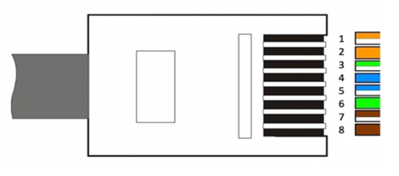
RS485 port 1 (connection 4)
| Pin | Function |
|---|---|
| 4 | B− |
| 5 | A+ |
| 8 | GND |
RS485 port 2 (connection 9) - optional
| Pin | Function |
|---|---|
| 4 | GND |
| 5 | A+ |
| 6 | B− |
Configuration
After connecting, the RS485 devices must be configured individually according to the manufacturer's manual. Each device in the RS485 network must be set as a slaveslave Een apparaat dat reageert op commando’s van de master. Elk apparaat heeft een uniek adres (ID). and assigned a unique Modbus address between 1 and 254.
The Envi.Baseenvi.base De energiecontroller van Envitron die apparaten uitleest, aanstuurt en data opslaat achter de hoofdaansluiting. uses the following communication settings by default:
baud rate 9600, 1 stop bit and parity none.
If a device deviates from this, it must be adjusted in the device's settings.
Once the devices are correctly configured, they can be added to the Envi.Baseenvi.base De energiecontroller van Envitron die apparaten uitleest, aanstuurt en data opslaat achter de hoofdaansluiting. via the Envitron installation tool.
In the tool, create the relevant device under the correct device category, select the appropriate communication settings
and give the device a clear name. This name will also be displayed as such in the portal.
Then test in the installation tool whether the measured values are displayed correctly.
If it is a controllable device, verify with a brief control signal that the device responds correctly.
Technical specifications
| Property | Specification |
|---|---|
| Recommended data cable | 2×0.75 mm² twisted pair with shielding |
| Maximum number of devices | 32 devices per bus |
| Maximum recommended distance | 400 m at 9600 baud |
| Maximum transmission speed | 115,200 baud (default 9600 baud) |
| Termination resistor | Typically 120 Ω, ¼ Watt. Always consult the manual of the connected device. |
Connection tips and points of attention
Faults
Is a device not coming online or is the bus responding slowly?
To diagnose the issue systematically, it is advisable to first get only the first device online and temporarily disconnect the rest of the bus.
Once this is successful, the remaining devices can be connected one by one. Check the following points:
- A and B are reversed
In most cases A is connected to A, but this is not a universal standard. Some brands, such as Janitza, require the A of the Envi.Baseenvi.base De energiecontroller van Envitron die apparaten uitleest, aanstuurt en data opslaat achter de hoofdaansluiting. to be connected to the B of the meter. If one device is connected incorrectly, the entire bus may go into fault. - Incorrect cable used
If no shielded twisted-pair cable has been used, interference may occur. Data can then drop out, causing devices to take a long time to be read. This risk increases when the data cable is routed close to power cables. - No termination resistor installed
Check whether a 120 Ω termination resistor has been placed between A+ and B− on the last device in the bus. - Termination resistor active in the wrong place.
Some devices have an internal terminator. Verify that this is only enabled on the last device. - Incorrect or duplicate Modbus address
Check that each device has a unique Modbus ID. An incorrect or duplicate address can disrupt communication on the entire bus. - Incorrect communication settings.
Check that all devices use the same communication parameters: baud rate 9600, 1 stop bit and parity none are the default values. Deviating settings will cause devices to not respond or only respond partially. - Incorrect bus signals
Measure between A and B with a multimeter. On an active RS485 bus, the voltage difference should be approximately ±2 V to ±3 V. A significantly higher or lower voltage often indicates a broken cable or a fault with the Envi.Baseenvi.base De energiecontroller van Envitron die apparaten uitleest, aanstuurt en data opslaat achter de hoofdaansluiting.. First rule out that the wiring is the cause. If the cable is in order, reset the Envi.Baseenvi.base De energiecontroller van Envitron die apparaten uitleest, aanstuurt en data opslaat achter de hoofdaansluiting. and check again. If the problem persists, contact the support department. - Defective communication board
If the above points have been checked and the problem persists, a communication board of an intermediate device may be defective. Disconnect the devices one by one and check each time whether the bus functions correctly afterwards.
Cable preparation
When a shielded cable without a drain wire is used, the cable sheath must be stripped back 5 cm. The braid must be unravelled and twisted into a "pigtail". Use heat-shrink tubing or insulating tape to finish this neatly. Strip both other conductors to 8 mm and fit a suitable ferrule to the ends.
When a shielded cable with a drain wire is used, the cable sheath must be stripped back 5 cm but the braid must also be cut away. A drain wire has been added to the conductors; make sure this is not cut off. Use heat-shrink tubing or insulating tape to finish the drain wire neatly. Strip the other conductors to 8 mm and fit a suitable ferrule to the ends. Some devices have no ground connection. In this case, the ground wire does not need to be connected. Bear in mind that the Envi.Baseenvi.base De energiecontroller van Envitron die apparaten uitleest, aanstuurt en data opslaat achter de hoofdaansluiting. should be placed as close as possible to the meters; without a ground connection, the network is more susceptible to interference.
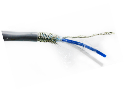
Twisted-pair RS485 data cable with shielding and reference wire (drain wire)
Ground / potential reference
In an RS485 bus, the third, uninsulated conductor in the bus cable is commonly referred to in practice as ground, but technically it is not an earth in the classical sense. It is a common reference, or potential reference, between all devices on the bus. This allows the devices on the bus to know within which voltage range the signal should fall. It ensures that A and B do not "float" somewhere and that the transceivers remain within their common-mode range. It is therefore about potential equalisation, so that everyone looks at the same electrical "floor". It is not a safety earth and is used solely for communication stability. Therefore, never connect it yourself to an earth rail, PE terminal or any other metal object.
If the cable has a separate reference wire that is not connected to the braid, the sheath may be connected to earth on one side. This will then not come into contact with the reference wire. Connecting to earth on one side prevents earth loops.